
Hay’s bridge for measurement of inductance :
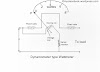
The Hay’s bridge is modification of the Maxwell’s bridge. The connection diagram of the Hay’s bridge is shown in figure below. This Hay's bridge uses a resistor in series with a standard capacitor (unlike the Maxwell’s bridge which uses a resistance in parallel with the capacitor).
- Hay's bridge for measurement of inductance

Let
L1=unknown resistance having a resistance R1,
R2, R3, R4=known non-inductive resistance,
C4=standard capacitor.
At balance,

Separating real and imaginary term, we obtain:

Solving the above two equations we have,

The Q factor of the coil is :

Advantages of the Hay’s bridge:
1) This bridge gives very simple expression for unknown inductance for high Q coils, and is suitable for coils having Q > 10.
2) This bridge also gives the simple expression for Q factor.
3) From expression of Q factor it is clear that for high Q factor the value of resistance R4 should be small.
Disadvantages of Hay’s bridge:
1) The Hay’s bridge is suited for measurement of high Q inductors, specially those inductors having Q > 10. For inductors having Q values smaller than 10, the term (1/Q)^2 in the expression for inductance L1 becomes rather important and thus cannot be neglected. Hence this bridge is not suited for measurement of coils having Q less than 10 and for thse applications a Maxwell's bridge is more suited.
If you like this article, please share it with your friends and like or facebook page for future updates. Subscribe to our newsletter to get notifications about our updates via email. If you have any queries, feel free to ask in the comments section below. Have a nice day!